mvpmc Hardware HowTo
Contributors:
Steve Tell
2005-05-22, v0.01.01
First release.
2006-05-10, v0.01.02
Added Steve's H1 serial port text and images.
2007-01-20, v0.01.03
Added another mvpmc user's hardware PDF notes about adding a 3 volt
TOSLINK interface.
2008-11-12, v0.01.04
Added section to track MVPMC IR Blaster effort.
The MediaMVP has some hidden talents that are not part of the out of
the box" offerings. First, we can add a digital output much like
the one many DVD players sport. Second we can add a serial port
which turns out to be the consul at boot up. To this, we can
connect a local display such that we can see what's playing. Many
thanks to the likes of BobTheBuilder and other's who hang out at
shspvr.com/forum!
SPDIF is a standard which can transfer audio and data streams over a
75 ohm cable in a digital format. For details search on these
standards: IEC958, IEC60958 and IEC61937. TOSLINK usually refers to
the optical version of SPDIF.
Hold it, before taking another step, be aware that opening your
MediaMVP box will probably void the warranty and making alterations
will certainly void the warranty. The HOWTO and MVPMC Code
authors and contributors are not responsible for any damage caused to
your MediaMVP box, to anything you connect to your MediaMVP box or to
your self.
Now that you feel totally on your own let's get started.
Seriously, if you haven't worked on static sensitive digital
circuits
before this may not be the right project for you. Taking static
precautions is just one of many procedural steps we are going to assume
you already know about. The only topic that will be covered here
is what has worked for other people with reference to adding a SPDIF
interface. If you would like to emulate what they did, that will be up
to you.
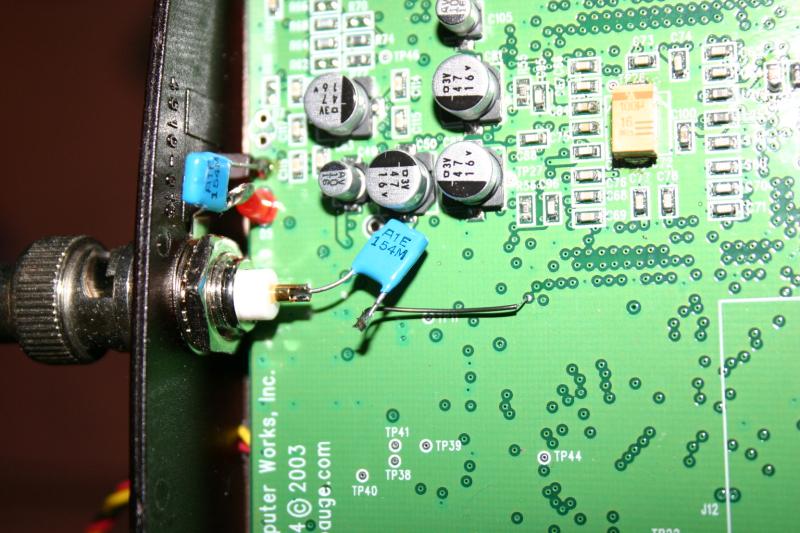
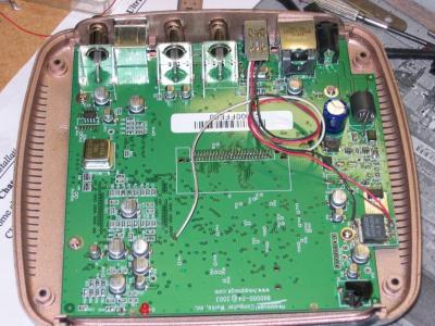
The SPDIF signal is already available inside the MediaMVP.
Locate TP60 by matching up the pattern on your printed circuit board
with the picture below (in this image, the front of the MediaMVP is to
the left). TP60 is where the capacitor is connected to the
circuit board near the center of the photograph (use a small gage wire
for this - probably at least AWG 30). Click on the picture for a
larger image. Thanks goes to BobTheBuilder for figuring out these
particulars and for this picture.
The SPDIF signal flows through this capacitor and onto the center of
the SPDIF connector. The other capacitor is used to AC couple the SPDIF
connector's shielded side to ground. Note the pad just above the
power LED should be a ground. This alteration is for an electrically
connected SPDIF port. Note the modification uses 2 capacitors to
isolate any DC component of the signal on both the signal and the
ground reference. In this alteration, the capacitors were each 0.1 uF
ceramic discs. This alteration uses a BNC connector. This
type of connector mounts solidly and makes secure and dependable
connections. Most home equipment will, however, use RCA
connectors and cables. Here's a circuit diagram in case you
really need one.
TP60 ----------------|(-------------> SPDIF signal to AMP
GND -----------------|(------------> SPDIF Ground for AMP
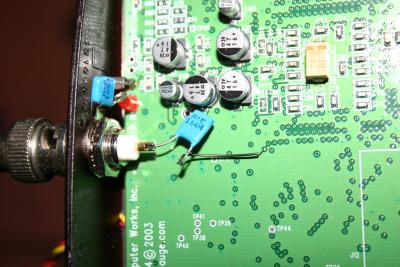
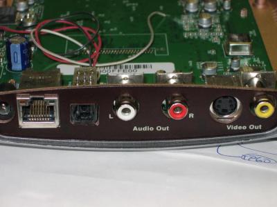
In a similar fashion one can add an optical TOSLINK. In the image below
the TOSLINK connector is located near the top (at the back of an
MediaMVP) between the Ethernet and left audio ports. The
connector is mounted up-side-down and covered by a small circuit board
so as not to solder the wires directly to it's pins. The white
wire is connected to TP60, the red to the regulated +5v side of the
power regulator IC and the black to the ground tab of the power
regulator IC. These TOSLINK connectors have a small circuit
inside to drive the LED which is the reason they require a power
connection. Note the SPDIF signal at TP 60 is probably a 0 to 3
volt signal and this alteration works despite the TOSLINK being powered
at 5 volts. Please take a look at the specifications of the
TOSLINK connector / adapter you will use to make sure there will be no
problems.
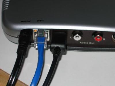
Here are some external views of the TOSLINK modification...
Yes! But it is missing a chip and some capacitors. It
turns out that this is the operating system's console. It comes
in
very handy for debugging. But we are mostly past that state
thanks to the efforts of the developers here.
On
the bottom of the circuit board, there is a "target" for a MAXIM MAX562
chip. There are also 6 capacitors missing (if I remember right). The MAX562
link should take you to a MAXIM web page which has a Typical Operating
Circuit diagram on it. There you can find appropriate
capacitor values. In the picture below all these parts have been
installed. Evidently the pads inside the white box to the right
were for a serial port header / connector. In this image the
black wire is connected to ground. This would go to pin 5 of a
DE9 female serial port connector. The red wire would go to pin 3
of the same connector. And the yellow would go to pin 2.
Thanks again to BobTheBuilder for pointing the rest of us in the right
direction and for this picture.
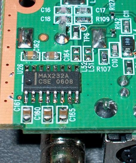
The MVP revision H1 has a slightly different circuit for
its serial console port.
The chip required is a
MAXIM
MAX232ACSE,
and the 5 0805-size capacitors should be 0.1uF.
Note that a MAX232 chip will probably not work; the "A" suffix
version is required.
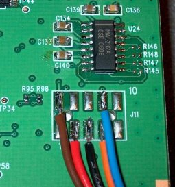
The pads labeled J11 are numbered correctly for wiring to
a DE9 serial connector wired as a DTE.
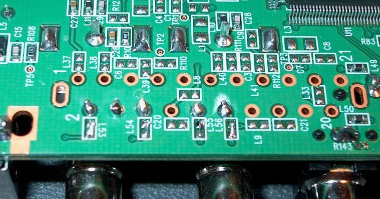
The MVP revision H1 has a chip location for a second serial port,
which can be accessed as /dev/ttyS02.
Required parts are another
MAX232ACSE and
5 more 0805-size capacitors.

This serial port is wired to the SCART connector pins through
tiny inductors. For a factory-correct version of this hack that might
pass RFI emission testing, suitable inductors must be installed. Otherwise,
the board locations labled L53, L54, L55, and L56 can be bridged with a tiny
wire.

In North American variants of the MVP, the SCART connector is not
installed, so wires from a DE9 connector can be soldered into the empty holes
out to a DE9 connector.
| Function | SCART pin | DE9 pin (DTE) |
GND | 4 | 5 |
TXD | 12 | 3 |
RXD | 6 | 2 |
RTS | 10 | 7 |
CTS | 2 | 8 |
VFD stands for Vacuum Fluorescent Display. Just about everyone
knows that LCD stands for Liquid Crystal Display. The main
differences are that VFDs generate their own light (usually a bright
blue), can be easily read at different angles, operate over a large
temperature range and can be viewed in bright light. LCDs are
passive (unless back lighted), and have contrast problems at different
angles and temperatures. For portable battery operated devices
LCDs wins hands down as they only take a fraction of the power to
operate. But for our application, I prefer VFDs.
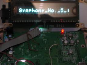
Here is a rather small VFD (1 row x 16 characters)
connected to the serial port of a MediaMVP running modified MVPMC
code. This particular unit is an used IEE VFD with a parallel
interface. The reseller included an Atmel processor base serial
to parallel board which makes it ideal for the MVPMC project. Click
on the image to download / view an AVI video of the display in action.
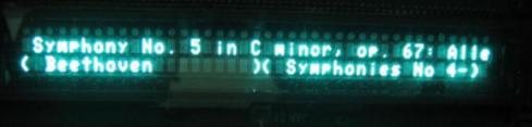
And here is a larger VFD (2 rows x 40 characters) connected to the same
serial port as above. Interestingly, I can use the same Atmel processor
base serial to parallel board for both IEE displays. Note, the larger display
has 2 extra pin and the pin-out is reversed so the Atmel board needs to be
plugged in up-side-down. Click on the image to download / view an AVI video
of the display in action.
Yes, there are more details that I didn't include. But I assume
most of you are experienced at this sort of thing and would be over
come by boredom if I dribbled on about how hard this was or easy that
can be. However, if I missed something, use the e-mail at the top
of this page and I'll try to update this HOWTO accordingly.
Thanks again to BobTheBuilder for his efforts and pictures.
Here is another user's hardware hacking notes about adding an optical
TOSLINK to his MVPMC box. It is a PDF file which you can view / down
load here:
HAUPPAGE_MEDIAMVP_TOSLINK_Installation_Summary.pdf.
It is a bit different as he wanted to power the TOSLINK transmitter with 3
volts because the chip driving the device is a 3 volt part. I agree where
the 3 volt power can be found. But disagree that the filter capacitor
lead is not a good connection point as well as I didn't find any resistance
between
that pin on the capacitor and the power regulator pin used for supplying
the 3 volts. However, I haven't tried this configuration, so there may be
problems that I don't see.
It's nicely written and there are plenty of pictures with extra graphics
to make is easy to understand. Thanks...
I'm going to drop in some IR remote control links here just to keep them
around. Also, I'm going to suggest that the mvpmc be used as an IR Blaster.
The first and simplest objective to this effort is to get rid of the TV
remote control (i.e. be able to use the mvpmc's remote for both the TV
and mvpmc box).
Linux Infrared Remote Control:
http://www.lirc.org/
HIFI-Remote (list of many remote control codes:
http://www.hifi-remote.com/ofa/
More links:
http://www.linux.org/docs/ldp/howto/Infrared-HOWTO/infrared-howto-c-lirc-irda.html
http://en.wikipedia.org/wiki/Amplitude-shift_keying
http://www.zen22142.zen.co.uk/Circuits/Interface/mod_det.htm